A while ago I got hold of this Shumatech DRO 350 kit to fit to my Sieg SX2 Mini Mill.
The mill is great for doing semi accurate stuff to layout lines and simple handwheel count jobs, but if you want to do things much more accurately much quicker a digital read out is the way to go. This kit creates a display and control unit that takes inputs from digital vernier calipers that you install onto each axis of the machine. The 350 does all sort of special features such as electronic edge finding and compensation for tool diameter and loads of things I don't even know about yet so it should make me and the mill much more capable.
The kit comes as a printed PCB (the one shown in a previous post), all components (including a pre-programmed PIC chip), connectors for interfacing the calipers to the board and a nice enclosure that has to be milled to suit the PCB buttons and display segments. This is then covered with a silk screened overlay.

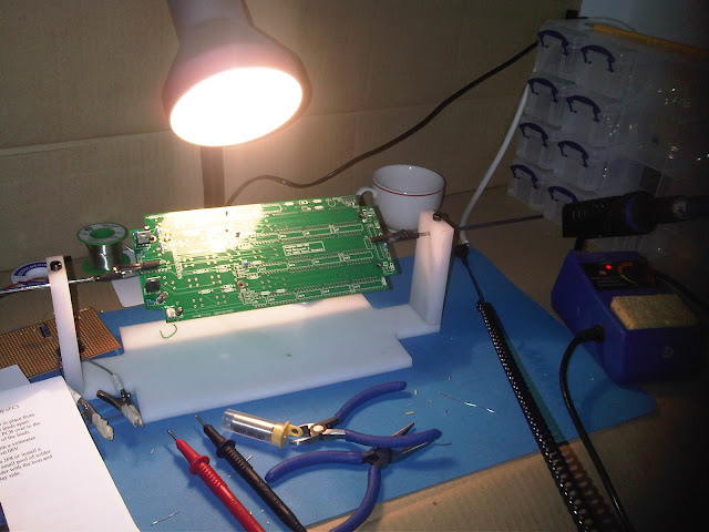
First thing was to knock up a static safe workspace to try and avoid wrecking the IC's.


Terrible photo (as most of them are) but I was quite happy to see the first banner line show up, meaning that I managed to not destroy anything with static or heat so far!

Knowing that the first line was good I then moved on to installing the second line of IC's and display segments, and got the second line I was hoping for. (It only displays the software version, the other two display blocks do work!)


With all the display related systems working I then moved on to installing the interface circuits for the scales.
Again more soldering of components and jumpers, everything looks alright but I need to get the calipers to actually test this part to see if it works.


Next step was to install the buttons, so yet more placing and soldering


Last components to be installed were the status/indicator LEDs above the top display line. With these done that's it for the actual PCB assembly, everything that I can test without the scales seems to work! Happy days.


A ground lead for the static mat was made up using some flex and a 1 megaohm resistor.


Then starts the very long process of placing and soldering components as per the diagrams and legends on the board. This took place over quite a few evenings just getting an hour or two when I could.


With most of the required basic components installed and the right voltages in the right places I could then install the first row of IC's that drive the first row of 7 segment displays and the PIC chip with the 'program'.

Terrible photo (as most of them are) but I was quite happy to see the first banner line show up, meaning that I managed to not destroy anything with static or heat so far!

Knowing that the first line was good I then moved on to installing the second line of IC's and display segments, and got the second line I was hoping for. (It only displays the software version, the other two display blocks do work!)


I ran out of small diameter solder at this point so seeing as I was on a roll I went down to Maplins to get some more and get some air as the room was getting a bit hazy from all the solder smoke!
After getting the solder the third row got seen to and ended with desired results.


With all the display related systems working I then moved on to installing the interface circuits for the scales.
Again more soldering of components and jumpers, everything looks alright but I need to get the calipers to actually test this part to see if it works.


Last components to be installed were the status/indicator LEDs above the top display line. With these done that's it for the actual PCB assembly, everything that I can test without the scales seems to work! Happy days.


Below is a short video of some button pressing
Next things to do now are to machine the enclosure suit the board and install all the ports and connectors on the back. I need to measure up the mill and design the attachments before I know what size scales I am going to get so will have to hold off on final testing till then, but it should be 'reeet.

Taa
Pete